Machine Vision Electronic Control board
This platform is associated to an electronic board for controlling : the translation of the conveyor, the activation of each sorting system, the activation of the lighting system.
Note
This board can be used to control 2 different step-motors.
Microcontroller
Pinouts
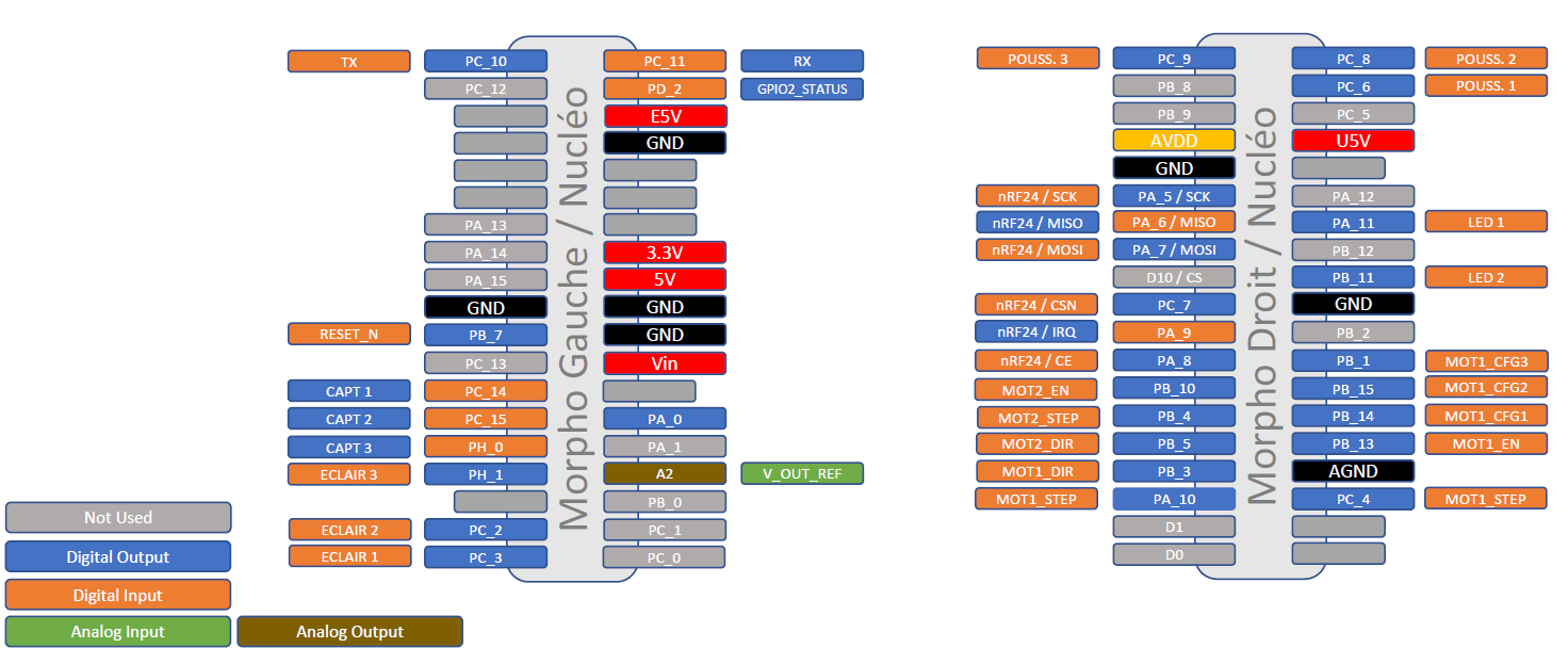
Pinouts of the board
Step-motor of the conveyor
The step-motor must be powered by a 4.6 to 4.8 V continuous source, connected to the J5 connector of the board.
Power stage and step motor driver
Two step-motors can be controlled independently by two TMC2100 (Kit TMC Silent Step Stick) drivers.
The first driver (Motor 1) can be configured by CFG1, CFG2 and CFG3 pins (see TMC2100 Documentation). The second driver (Motor 2) is already set up as CFG3=open (External reference voltage on pin AIN), CFG2/1=0b01 (HalfSteps).
TMC2100 |
Elec Board |
Nucleo Board |
|---|---|---|
EN (In) |
MOT1_EN (Out) |
PB_13 |
DIR (In) |
MOT1_DIR (Out) |
PB_3 |
STEP (In) |
MOT1_STEP (Out) |
PA_10 |
CFG1 (In) |
MOT1_CFG1 (Out) |
PB_14 |
CFG2 (In) |
MOT1_CFG2 (Out) |
PB_15 |
CFG3 (In) |
MOT1_CFG3 (Out) |
PB_1 |
VREF_AIN (Analog In) |
V_OUT_REG (Analog Out) |
PA_4 / A2 |
To configure CFG3 as open pin, the J2 jumper must be removed (External reference voltage on pin AIN). To connect the CFG3 input pin of the TMC2100 driver to the Nucleo Board (MOT1_CFG3 pin), the J2 jumper must be in place.
TMC2100 |
Elec Board |
Nucleo Board |
|---|---|---|
EN (In) |
MOT2_EN (Out) |
PB_10 |
DIR (In) |
MOT2_DIR (Out) |
PB_5 |
STEP (In) |
MOT2_STEP (Out) |
PB_4 |
VREF_AIN (Analog In) |
V_OUT_REG (Analog Out) |
PA_4 / A2 |
An external power supply must be connected to the J5 connector (VMOT). This nominal supply for the xxx step-motor is 4V, for a maximal current of 1A per phase.
More details on the TMC2100 Documentation.
A library for TMC2100 and an example of use is available : TMC2100 Library and example.
Presence sensors
Three digital inputs are dedicated to SEN0239 infrared presence detectors, including supply of the sensors.
Sensor |
Elec Board |
Nucleo Board |
|---|---|---|
Sensor 1 |
CAPT1 (In) |
PC_14 * |
Sensor 2 |
CAPT2 (In) |
PC_15 * |
Sensor 3 |
CAPT3 (In) |
PH_0 |
Warning
Don’t use PC_14 and PC_15 ! Not connected on the Nucleo board CN7 connector. Bad design :/
Communication
A RN41/42 XV module or a nrF24L01 module could be implemented for radio-frequency communication.
BlueTooth communication via RN41/42 module
RF communication via nRF24L01 module
nRF24L01 |
Elec Board |
Nucleo Board |
|---|---|---|
SCK / In |
nRF24 / SCK (Out) |
PA_5 / D13 * |
MISO / Out |
nRF24 / MISO (In) |
PA_6 / D12 |
MOSI / In |
nRF24 / MOSI (Out) |
PA_7 / D11 |
CSN / In |
nrF24 / CSN (Out) |
PC_7 |
IRQ / Out |
nrF24 / IRQ (In) |
PA_9 |
CE / In |
nrF24 / CE (Out) |
PA_8 |
LED1 (LD2 on board led) could not be used if nrF24 is connected
Lighting system
The lighting system is an EFFI-Ring from the Effilux company, type RGB (ref ??). Red, Blue and Green lights can be controlled independently.
IMAGE OF THE LIGHT
A M12-5pins connector is used to control and power the ring. The power supply is 24V. The pins controlling the 3 independent sources are connected to a MOSFET transistor.
Light Source |
Elec Board |
Nucleo Board |
|---|---|---|
Red |
ECLAIR 1 |
PC_3 |
Green |
ECLAIR 2 |
PC_2 |
Blue |
ECLAIR 3 |
PH_1 |
Lights are activated on a low-level state of the previous outputs (output = 0).
An external power supply must be connected to the J19 connector (V_ECLAIRAGE). The nominal supply for the EFFi-Ring source is 24V.
More details on the EFFI-Ring Documentation.