TUNIS board tests procedures
Signal processing
In this section, the signal processing part of the board will be tested.

TUNIS board - Analog inputs and outputs
Binary file
Procedure
Step1
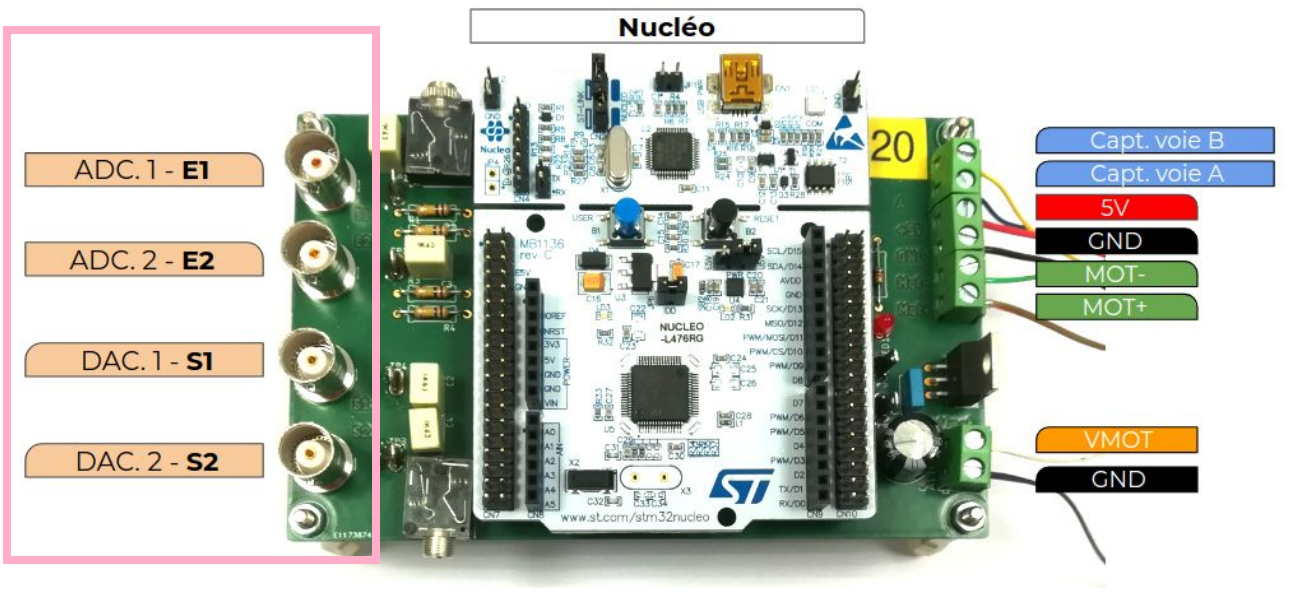
Apply a signal with a function generator on the E1 and E2 analog inputs, with those parameters :
Shape : sine
Frequency : 100 Hz
Amplitude : 1 V peak to peak
Offset : 1.65 V
Step 2
Connect the S1 and S2 analog outputs to an oscilloscope.
Step 3
Upload the binary file to the Nucleo board.
The output signals are the same as the input signals, but with samples of 100 us duration.
Code explanation
DC Motor position control
In this section, the DC motor position control part of the board will be tested.

TUNIS board - DC motor connector
Binary file
Procedure
To test the board in this mode, you have to follow the next steps.
Step 1
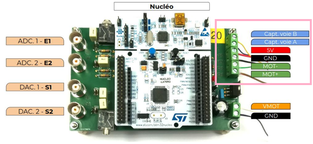
Connect a DC motor (Pololu 3239 or 4843) to the right connector of the board (see previous figure).
Color |
Function |
|---|---|
Red |
Motor power (connected to one motor terminal) |
Black |
Motor power (connected to the other motor terminal) |
Green |
Encoder GND |
Blue |
Encoder VCC (5V) |
Yellow |
Encoder A output |
White |
Encoder B output |
Step 2
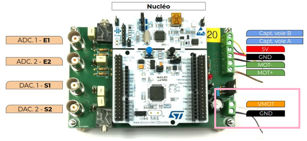
Connect a power supply on the right connector called VMOT.

TUNIS board - Power supply of the motor
VMOT must be a voltage between 6 and 12V (for Pololu motors).
GND must be connected to the ground of the previous power supply.
Step 3
Apply a signal with a function generator on the E1 analog input, with those parameters :
Shape : square
Frequency : 0.3 Hz
Amplitude : 1 V peak to peak
Offset : 1.65 V
Symetry : 50 %
Step 4
Upload the binary file to the Nucleo board.
Caution
After the binary file upload, the DC motor starts to rotate at a specific speed if the power supply is switched on.
At the beginning of the program, an initialization phase makes the motor rotates at a specific speed in one direction during 1 second, then stops the motor during 1 second, then restarts the motor in the opposite direction at a different speed during 1 second and finally stops the motor during 1 seconde.
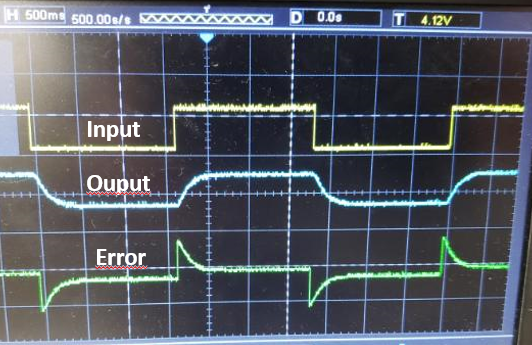
The next part of the program controls the position of the DC motor depending on the setpoint signal on E1 analog input. The motor turns in one direction until it is stabilized at a specific position, then turns in the other direction.
Step 5 (optionnal)
Connect the S1 (error signal of the controller) and S2 (ouput signal of the controller) outputs to an oscilloscope.

TUNIS board - DC motor control in position - signals