Schematics - MIDI 2 DMX Platform
L476RG version
DMX extension - revision 3
Caution
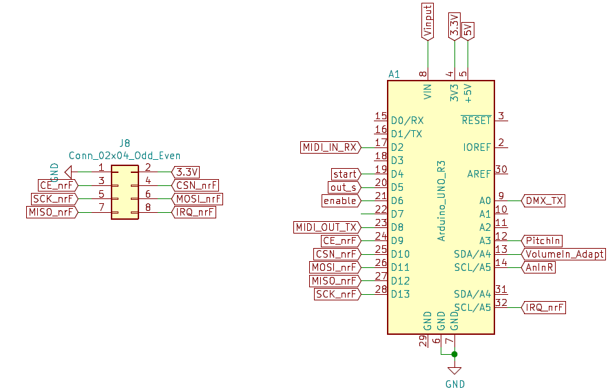
On this version, the nRF24 connector can not be used. You need the MIDI extension.
Note
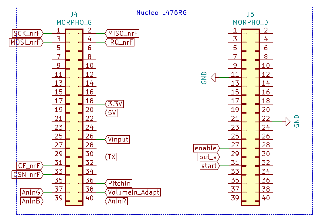
The DMX extension is a motherboard for the STM Nucleo board. It uses the Morpho connectors.
The Nucleo morpho connectors schematic :
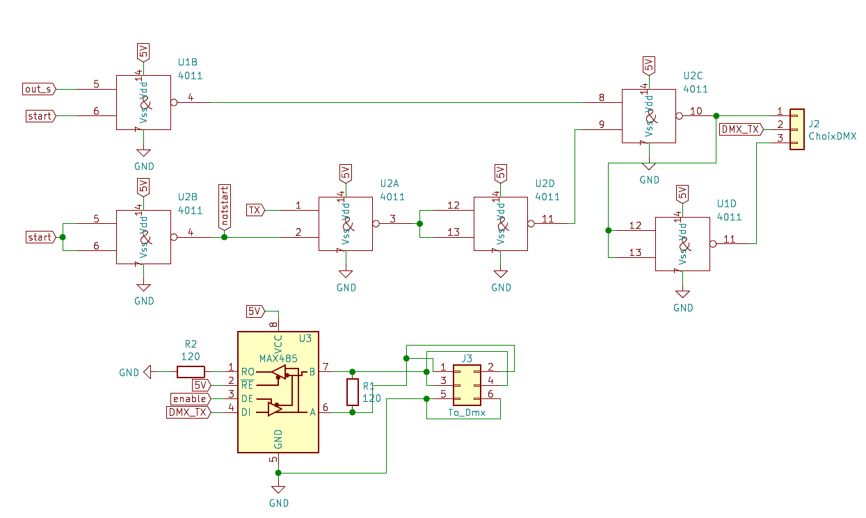
The output DMX signal is generated as mentionned in the next figure, to respect the timing of the protocol.

Four signals are used to generate the perfect timing : start, out_s, enable and TX (serial output used for transmitting data).
A MAX485 low-power transceiver is used for RS-485 communication on the DMX bus.
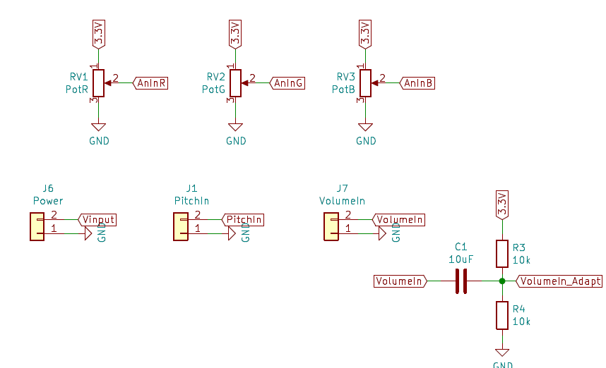
Three potentiometers (RV1, RV2 and RV3) can be used on the board and are connected to three analog inputs.
Two analog inputs can also be used (PitchIn - J1 - and VolumeIn - J7). The VolumeIn input is a filtered (15Hz high-pass first order filter) input with an offset compatible with Nucleo analog-to-digital converter.
An external power supply between 7 to 12V can be used on the J6 connector.
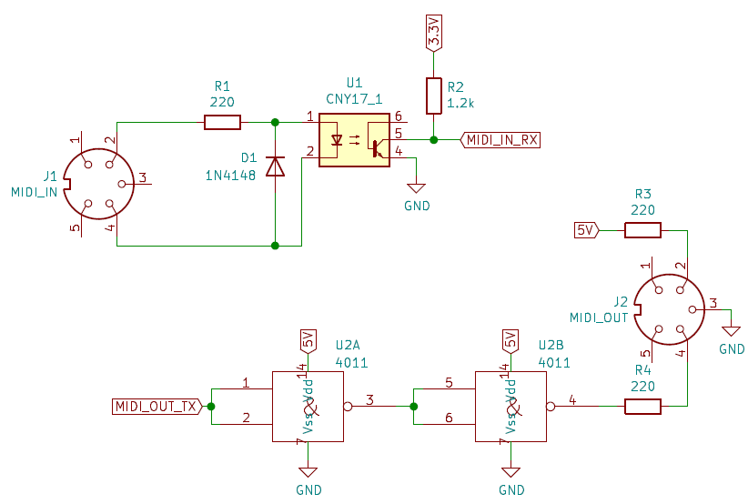
MIDI extension
Note
The MIDI extension uses the Arduino connectors of the Nucleo board.
